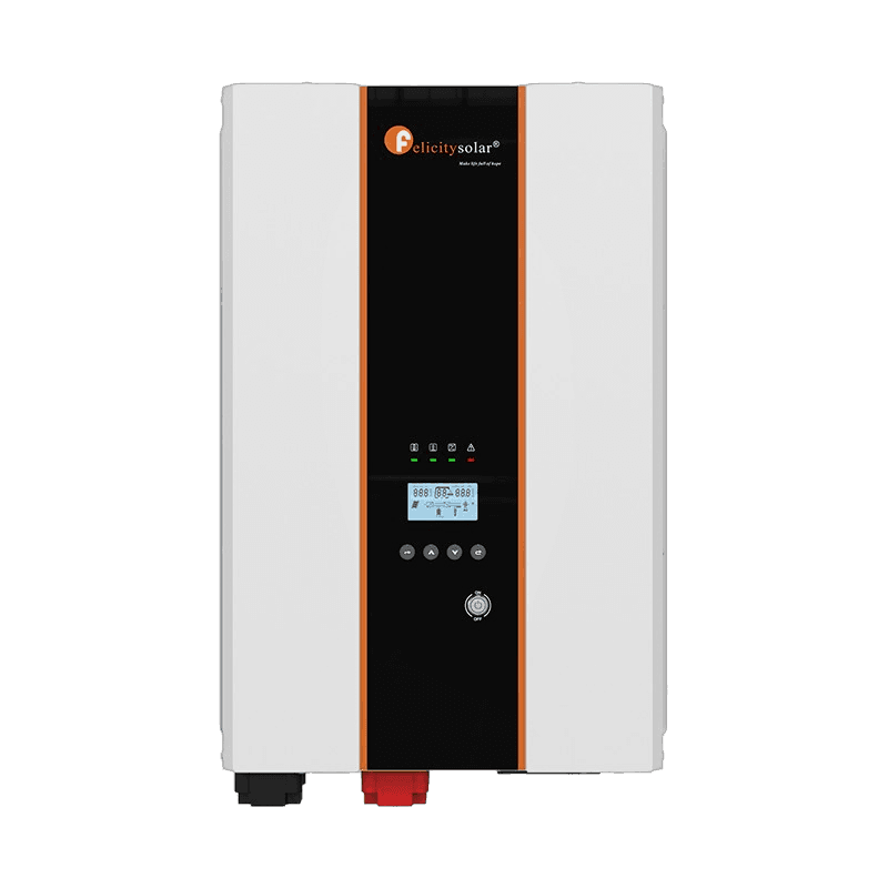
Felicity Solar IVPS10048P2G1 8000W Inverter / Charger
- Rated Output Power (Va):10000VA
- Rated Output Power (W):8000W
AED 1,750
Buy Now — Felicity Solar IVPS10048P2G1 8000W Inverter / ChargerThis is the complete fault table for the Felicity IVPS3524P1G1-LV Inverter family — 28 codes shared by 6 model numbers, transcribed from the official manual. On Felicity units, a fault code means the unit has cut its output and the red LED stays solid; a warning flashes the red LED while the unit keeps running.
Last checked against the official manuals on 10 July 2026.
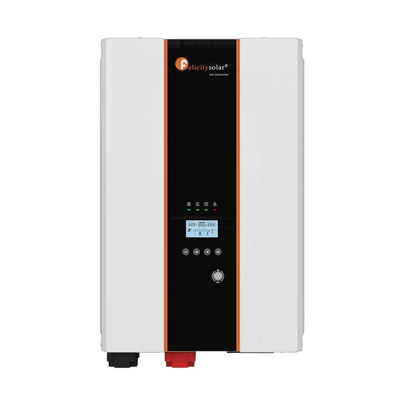
The inverter is overloaded and cuts off its output; the red LED is solid on.
CauseThe connected load exceeds the rated output power of the inverter while running in battery mode.
Recommended fixTurn off the inverter, decrease the load to less than the rated output power of the inverter, then turn the inverter on again. If the overload happens while the AC input is on, wait 30 seconds and the fault will clear automatically.
Source:ivps3524p1g1-lv-ivps5048p1g1-lv-ivps7548p2g1-ivps10048p2g1-manual.pdf· page 24
The inverter output voltage is above the allowed range.
CauseThe inverter measured its own AC output voltage above the permitted range. Output voltage is regulated entirely inside the unit, so this points to an internal regulation or feedback fault rather than a wiring issue.
Recommended fixRestart the inverter. If the fault persists, contact the repair center.
Source:ivps3524p1g1-lv-ivps5048p1g1-lv-ivps7548p2g1-ivps10048p2g1-manual.pdf· page 24
A short circuit is detected on the inverter AC output.
CauseThe AC output wiring or a connected load is short-circuited.
Recommended fixIf the AC input is on, cut off the AC input first, then turn off the inverter, disconnect all AC output wiring and turn it on again. If the screen still displays the fault, contact the repair center. If the inverter can work again, check the output wiring and load and make sure none of them are short-circuited.
Source:ivps3524p1g1-lv-ivps5048p1g1-lv-ivps7548p2g1-ivps10048p2g1-manual.pdf· page 24
The battery voltage is above the allowed maximum.
CauseThe battery voltage is too high; on a 48V system a reading above 60V indicates a battery problem.
Recommended fixRead the battery voltage from the screen and measure the battery voltage with a multimeter. If both readings are more than 60V, the battery may have a problem and you must stop using it.
Source:ivps3524p1g1-lv-ivps5048p1g1-lv-ivps7548p2g1-ivps10048p2g1-manual.pdf· page 24
The internal temperature of the inverter is too high.
CauseThe inverter has overheated.
Recommended fixTurn off the inverter and let it cool down. After the temperature is back to normal you can use it again.
Source:ivps3524p1g1-lv-ivps5048p1g1-lv-ivps7548p2g1-ivps10048p2g1-manual.pdf· page 24
Over current is detected while charging the battery.
CauseWhile charging the battery, current through the charger stage exceeded its protection limit. The trip is raised by the internal charging circuit, so persistent recurrence indicates a charger-stage fault rather than a battery wiring problem.
Recommended fixContact the repair center.
Source:ivps3524p1g1-lv-ivps5048p1g1-lv-ivps7548p2g1-ivps10048p2g1-manual.pdf· page 24
The inverter soft start did not complete in time.
CauseAt power-up the soft-start ramp failed to bring the inverter stage to its working point within the allowed time — an internal power-stage or pre-charge fault.
Recommended fixContact the repair center.
Source:ivps3524p1g1-lv-ivps5048p1g1-lv-ivps7548p2g1-ivps10048p2g1-manual.pdf· page 24
The inverter output voltage is below the allowed range.
CauseA high-power load is dragging the output voltage down, or an internal fault has triggered.
Recommended fixTurn off the inverter, disconnect all AC output wiring and then turn it on. If it still shows the fault, contact the repair center. If it works normally, check whether the output is connected to a big power load; disconnect the big load, turn on the inverter and confirm it can work normally.
Source:ivps3524p1g1-lv-ivps5048p1g1-lv-ivps7548p2g1-ivps10048p2g1-manual.pdf· page 24
The battery is disconnected from the inverter.
CauseThe battery connector is loose or disconnected.
Recommended fixCheck the battery connector.
Source:ivps3524p1g1-lv-ivps5048p1g1-lv-ivps7548p2g1-ivps10048p2g1-manual.pdf· page 24
The internal current sensor reports an abnormal value.
CauseThe inverter's internal current sensor returned an out-of-range or implausible reading, so the control board can no longer trust its output-current measurement.
Recommended fixContact the repair center.
Source:ivps3524p1g1-lv-ivps5048p1g1-lv-ivps7548p2g1-ivps10048p2g1-manual.pdf· page 25
The inverter temperature sensor (NTC) is disconnected or abnormal.
CauseThe inverter temperature sensor wiring is disconnected or the sensor failed.
Recommended fixContact the repair center.
Source:ivps3524p1g1-lv-ivps5048p1g1-lv-ivps7548p2g1-ivps10048p2g1-manual.pdf· page 25
The output is heavily overloaded or short-circuited.
CauseA heavy overload or a short circuit is present on the AC output.
Recommended fixRefer to the handling for fault 13 (overload) and fault 15 (output short).
Source:ivps3524p1g1-lv-ivps5048p1g1-lv-ivps7548p2g1-ivps10048p2g1-manual.pdf· page 25
CAN communication data is lost between inverters in the parallel system.
CauseParallel communication cables between inverters are loose, damaged or not connected well.
Recommended fixCheck if the communication cables are connected well and restart the inverter. If the problem remains, contact your installer.
Source:ivps3524p1g1-lv-ivps5048p1g1-lv-ivps7548p2g1-ivps10048p2g1-manual.pdf· page 25
Host communication data is lost between inverters in the parallel system.
CauseParallel communication cables between inverters are loose, damaged or not connected well.
Recommended fixCheck if the communication cables are connected well and restart the inverter. If the problem remains, contact your installer.
Source:ivps3524p1g1-lv-ivps5048p1g1-lv-ivps7548p2g1-ivps10048p2g1-manual.pdf· page 25
Synchronization data is lost between inverters in the parallel system.
CauseParallel communication cables between inverters are loose, damaged or not connected well.
Recommended fixCheck if the communication cables are connected well and restart the inverter. If the problem remains, contact your installer.
Source:ivps3524p1g1-lv-ivps5048p1g1-lv-ivps7548p2g1-ivps10048p2g1-manual.pdf· page 25
In the parallel system, the inverters measure different battery voltages.
CauseThe inverters do not share the same battery group, or the battery cables differ in length or material type.
Recommended fixMake sure all inverters share the same groups of batteries. Remove all loads and disconnect the AC input and PV input, then check the battery voltage of all inverters. If the values from all inverters are close, check that all battery cables are the same length and material type; otherwise, contact your installer to provide the SOP to calibrate the battery voltage of each inverter. If the problem still remains, contact your installer.
Source:ivps3524p1g1-lv-ivps5048p1g1-lv-ivps7548p2g1-ivps10048p2g1-manual.pdf· page 25
The inverters in the parallel system detect different AC input voltage or frequency.
CauseThe utility wiring differs between inverters, or the units do not receive utility power at the same time.
Recommended fixCheck the utility wiring connection and restart the inverter. Make sure the utility starts up at the same time; if there are breakers installed between the utility and the inverters, make sure all breakers can be turned on at the AC input at the same time. If the problem remains, contact your installer.
Source:ivps3524p1g1-lv-ivps5048p1g1-lv-ivps7548p2g1-ivps10048p2g1-manual.pdf· page 25
The AC output current differs too much between inverters in the parallel system.
CauseExcessive loads, or AC input and output cables of different length or material type between inverters.
Recommended fixRestart the inverter. Remove some excessive loads and re-check the load information from the LCD of the inverters. If the values are different, check that the AC input and output cables are the same length and material type. If the problem remains, contact your installer.
Source:ivps3524p1g1-lv-ivps5048p1g1-lv-ivps7548p2g1-ivps10048p2g1-manual.pdf· page 25
The AC output mode (LCD setting #28) is not set consistently across the parallel system.
CauseLCD program #28 is set to different output modes on the paralleled inverters.
Recommended fixSwitch off the inverter and check LCD setting #28. For a parallel system in single phase, make sure no 3P1, 3P2, 3P3, 2P1 or 2P2 is set on #28. For supporting three-phase systems, make sure no PAL, 2P1 or 2P2 is set on #28. For supporting split-phase systems, make sure no PAL, 3P1, 3P2 or 3P3 is set on #28. If the problem remains, contact your installer.
Source:ivps3524p1g1-lv-ivps5048p1g1-lv-ivps7548p2g1-ivps10048p2g1-manual.pdf· page 25
Power is feeding back into the inverter output.
CauseL and N cables are connected reversely, or sharing cables are wired between inverters on different phases.
Recommended fixRestart the inverter. Check if the L and N cables are not connected reversely in all inverters. For a parallel system in single phase, make sure the sharing cables are connected in all inverters; for three-phase or split-phase systems, make sure the sharing cables are connected in the inverters on the same phase and disconnected in the inverters on different phases. If the problem remains, contact your installer.
Source:ivps3524p1g1-lv-ivps5048p1g1-lv-ivps7548p2g1-ivps10048p2g1-manual.pdf· page 26
The inverters in the parallel system run different firmware versions.
CauseThe CPU firmware versions of the paralleled inverters differ.
Recommended fixUpdate all inverter firmware to the same version. Check the version of each inverter via the LCD setting and make sure the CPU versions are the same; if not, contact your installer to provide the firmware to update. After updating, if the problem still remains, contact your installer.
Source:ivps3524p1g1-lv-ivps5048p1g1-lv-ivps7548p2g1-ivps10048p2g1-manual.pdf· page 26
The output current differs between inverters in the parallel system.
CauseThe current-sharing cables are loose or not connected well.
Recommended fixCheck if the sharing cables are connected well and restart the inverter. If the problem remains, contact your installer.
Source:ivps3524p1g1-lv-ivps5048p1g1-lv-ivps7548p2g1-ivps10048p2g1-manual.pdf· page 26
Overload warning; the code flashes on the LCD and the red LED flashes.
CauseThe connected load is above the inverter's rated output power.
Recommended fixReduce the connected load. The inverter forbids overload; the remaining working time depends on the percent of load.
Source:ivps3524p1g1-lv-ivps5048p1g1-lv-ivps7548p2g1-ivps10048p2g1-manual.pdf· page 27
The battery voltage is too low.
CauseThe battery is discharged below the low-voltage warning level.
Recommended fixThe voltage of the battery is too low; the battery should be charged.
Source:ivps3524p1g1-lv-ivps5048p1g1-lv-ivps7548p2g1-ivps10048p2g1-manual.pdf· page 27
The inverter derates its output power because the utility voltage is low.
CauseThe AC input voltage is low (about 90-170V).
Recommended fixRead the voltage from the screen and confirm the voltage of the AC input is about 90-170V. If it is, the AC input voltage is low and the unit can work normally. If not, contact the repair center.
Source:ivps3524p1g1-lv-ivps5048p1g1-lv-ivps7548p2g1-ivps10048p2g1-manual.pdf· page 27
The transformer temperature sensor (NTC) is disconnected.
CauseThe transformer temperature sensor wiring is disconnected or the sensor failed.
Recommended fixContact the repair center.
Source:ivps3524p1g1-lv-ivps5048p1g1-lv-ivps7548p2g1-ivps10048p2g1-manual.pdf· page 27
The inverter temperature sensor (NTC) is disconnected.
CauseThe inverter temperature sensor wiring is disconnected or the sensor failed.
Recommended fixContact the repair center.
Source:ivps3524p1g1-lv-ivps5048p1g1-lv-ivps7548p2g1-ivps10048p2g1-manual.pdf· page 27
The AC input phase is abnormal. Shown as flashing warning code 14 on the LCD (distinct from solid fault code 14, output voltage high).
CauseThe AC input phase is abnormal.
Recommended fixContact the repair center.
Source:ivps3524p1g1-lv-ivps5048p1g1-lv-ivps7548p2g1-ivps10048p2g1-manual.pdf· page 27
Support for your Felicity unit is free for life — our contact page lists our phone and email. If the unit needs replacing, order it online.
Compiled from official Felicity user manuals. Always consult your device manual and a qualified technician before performing repairs.