Panels that will not fit the inverter you already own, and a battery bank you cannot grow without replacing it — both come from taking four decisions in the wrong order. Here is the order, and what each step rules out for the one after it.
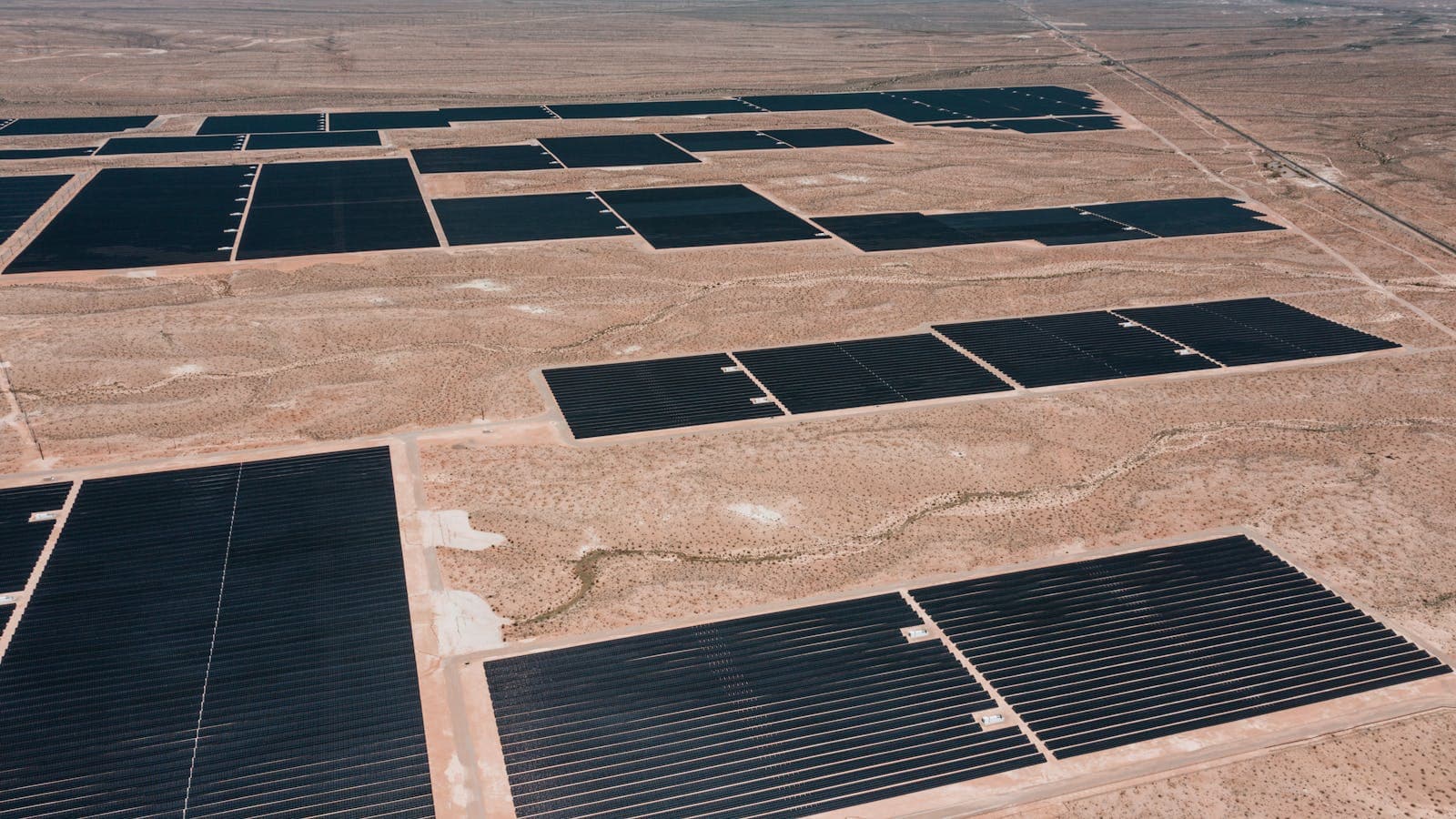
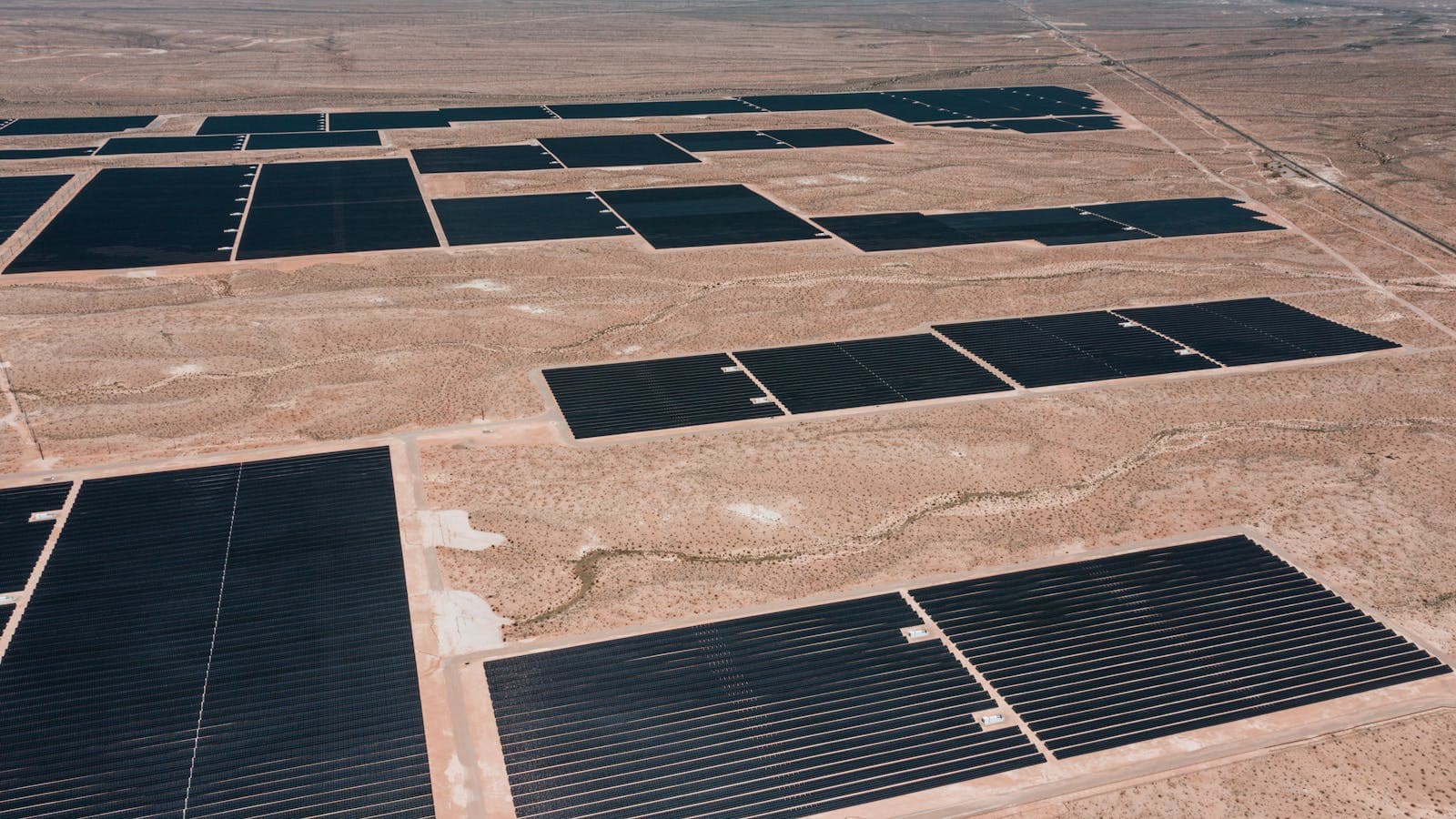
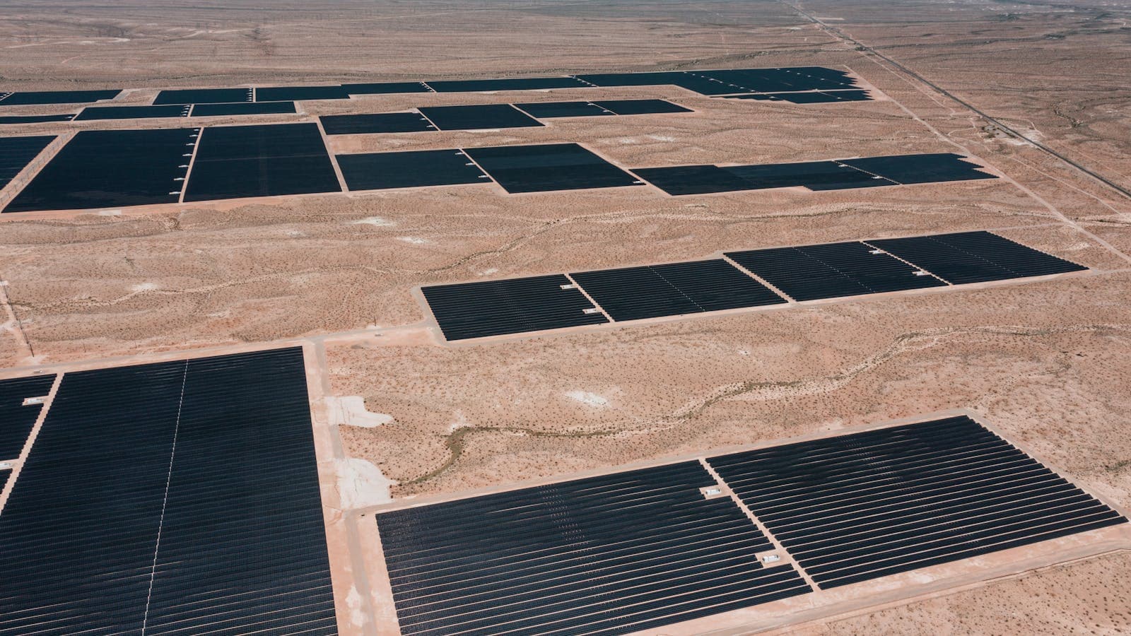
The two most expensive mistakes on a farm system are panels that will not fit the inverter you already own, and a battery bank you cannot grow without throwing away the one you started with. Both come from the same cause: four decisions taken in the wrong order. Electrifying a whole holding is a different job from powering one well, and those four — the array, the charge controller, the battery bank and the second source — have to be taken in sequence, because each one narrows the next. We are the authorised Felicity Solar distributor supplying Saudi Arabia from our own stock, and this is the build sequence we walk Eastern Province farms through.
Two things are deliberately not in this guide, so that nothing is repeated. Why the market looks the way it does around Al Ahsa is in the Saudi off-grid overview. Everything about a motor's starting behaviour — the surge row, the overload trip times, the battery's peak current — belongs to the pump sizing guide and is not restated here.
First decision: does the inverter carry the array, or does a controller?
Felicity's off-grid families answer this very differently, and the difference is visible on the listings as a presence or an absence of rows.
- The IVPS family prints no solar input rows at all. It is an inverter/charger: the array does not connect to it, it connects to the bank through a separate charge controller. That is not a shortcoming, it is an architecture, and on a farm that intends to grow the array later it is often the more flexible one.
- The IVPM family is the same platform with a tracker built in: 1 MPPT tracker, an MPPT voltage range of 65-145 V, a maximum PV voltage of 170 V and a maximum PV input power of 6.6 kW, with 1 string per MPPT.
- The IVBM8048P1G1 prints 1 MPPT tracker with a 100-450 V range, a 450 V ceiling, 5 kW + 5 kW of PV input power and 2 strings per MPPT. The IVBM10048P1G1 prints 5.5 kW + 5.5 kW.
- The IVAM8048P1G1 prints 2 MPPT trackers, a 90-425 V range with a full-load range of 200-425 V, a 500 V ceiling, 16 kW of PV input power and 2+2 strings per MPPT. The IVAM10048P1G1 prints 20 kW and the IVAM12048P1G1 prints 24 kW.
- The IVEM family sits between them — the IVEM5048 prints 1 MPPT with a 120-500 V range, a 500 V ceiling and 6 kW of PV input power, while the IVEM6048-II prints a 90-450 V range and 7.5 kW.
Read those as four different shapes of input rather than as bigger and smaller versions of one thing. An array that suits an IVAM will not physically fit an IVPM, and the reverse is equally true.
Second decision: how many panels in a row before it is too many
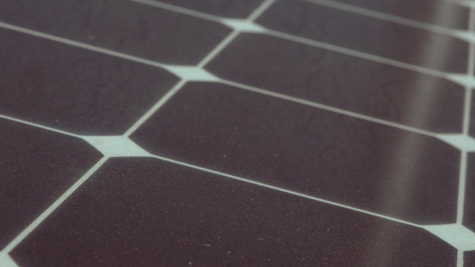
The panel decides how the array can be arranged, and every figure needed is on its own page. The GK-1-72HTBD-580M prints a rated maximum power of 580 W, an open-circuit voltage of 51.47 V, a voltage at maximum power of 42.59 V, a short-circuit current of 14.37 A and a maximum power current of 13.62 A. It also prints a maximum system voltage of DC1500V, a maximum series fuse of 30 A, and a temperature coefficient of open-circuit voltage of -0.25 % per °C.
Now put the panel against the inverter windows above and the constraint becomes arithmetic rather than opinion.
On an IVPM, whose ceiling is 170 V: three panels in series give 3 × 51.47 = 154.41 V open-circuit, which is inside the ceiling, and 3 × 42.59 = 127.77 V at maximum power, which sits inside the 65-145 V tracking window. Four panels in series give 4 × 51.47 = 205.88 V, which is over the ceiling and must not be connected. That is why the IVPM's 6.6 kW input limit is reached with short strings and more of them.
On an IVAM8048P1G1, whose ceiling is 500 V: eight panels in series give 8 × 51.47 = 411.76 V open-circuit and 8 × 42.59 = 340.72 V at maximum power, comfortably inside both the 500 V ceiling and the 90-425 V tracking range, and inside the 200-425 V full-load range as well. The same panel, the same farm, a completely different array layout.
One warning that costs systems every year: open-circuit voltage rises as cell temperature falls, and the panel's own coefficient of -0.25 % per °C is what quantifies it. Apply that coefficient to the lowest cell temperature your site actually reaches — a figure that belongs to your site and that we will not invent for you — and check the result against the ceiling, not the room-temperature number. A string that is comfortable at midday can exceed the inverter's maximum PV voltage on a cold morning, and that is a hardware failure rather than a fault code.
Voltage is only half of it; the other half is current. The IVAM8048P1G1 prints a maximum PV input current of 27+27 A and a maximum short-circuit current of 40+40 A, and the IVBM8048P1G1 prints 20+20 A. Facing them, the panel prints a maximum power current of 13.62 A, a short-circuit current of 14.37 A and a maximum series fuse of 30 A. Read those rows together before deciding how many strings go in parallel on one tracker, because the string count is bounded by current as well as by the strings-per-MPPT row on the same page.
Third decision: whether an external charge controller earns its place
A separate MPPT controller does two things the inverter's own input cannot. It lets the array be larger than the inverter's PV input power limit, and it lets the array live at a voltage the inverter would refuse.
The SCCM15048 prints a nominal system voltage of 48 V, a maximum charge current of 150 A, a maximum solar input voltage of 500 V, an MPPT voltage range of 150-450 Vdc, a maximum input power of 9000 W and a maximum efficiency of 98 %. It also prints IP54, RS485 and CAN over MODBUS with Bluetooth and WiFi built in, a three-step charging algorithm of bulk, absorption and float with an absorption voltage of 57.6 V and a float voltage of 54.4 V, and support for lithium, AGM, GEL, flooded and user-defined battery types. Its PV start-up voltage is 120 V, which is a real design input: with the panel above, three in series give 127.77 V at maximum power, so a shorter string simply will not wake it.
The SCCM10048-II is the smaller answer: 100 A maximum charge current, a maximum solar input voltage of 195 V, an MPPT range at 48 V of 60-170 VDC, a maximum input power at 48 V of 5500 W, a PV start-up voltage of 15 V, transient surge protection of 4500 W per port and an enclosure rating of IP20 marked "Indoor & Vented". Note the enclosure difference against the SCCM15048's IP54 — on a farm that decides where the box can physically go.
Pairing an IVPS with an SCCM is therefore not a workaround. It is the configuration that lets a 48 V holding take a high-voltage array today and a bigger one next season without touching the inverter.
Fourth decision: the battery, sized from what is printed rather than a rule of thumb
Two rows turn a battery's nameplate into a usable number, and both are printed. The FLA48300 prints a nominal energy of 15 kWh and a depth of discharge of ≥95 %, so at least 14.25 kWh of that is available to the site. The FLA48400TG1 prints 20.48 kWh and a depth of discharge of 95 %, which is 19.46 kWh usable. The FLA48200 prints 10 kWh at >95 %.
How far the bank can grow is a printed row too. All three packs print a maximum of 15 parallel units, with maximum system capacities of 225 kWh on the FLA48300, 307.2 kWh on the FLA48400TG1 and 150 kWh on the FLA48200. The honest advice is therefore to start at the capacity today's loads justify, inside a family you can extend.
Longevity sits on the same page: the FLA48300 prints a cycle life of 6000 and the FLA48400TG1 prints >6000. Communications differ — CAN and RS485 on the FLA48300, CAN2.0, RS485, Wi-Fi and Bluetooth on the FLA48400TG1 — and so does certification: the FLA48300 prints UN38.3, CE-EMC and IEC 62619.
One last match is easy to forget: the bank's voltage window has to sit inside the inverter's battery voltage window. The FLA48300 prints an operating voltage of 44.8-57.6 V and a cut-off voltage of 44.8 V. The IVPS and IVPM families print a battery voltage range of 42-63 V, the IVBM8048P1G1 prints 42-60 V and the IVAM8048P1G1 prints 40-60 V. Compare the two rows before ordering rather than after wiring, because a bank that cuts off at a voltage the inverter does not expect produces behaviour that looks like a fault and is really a mismatch.
The lead-acid alternative, stated honestly
Some farms would rather build a bank from individual cells, and the OPzV range exists for exactly that. The FL-OPzV-1000AH-2V prints 2 V, 1000 Ah, 2 kWh of nominal energy, a gel tubular-plate VRLA construction, a maximum charging current of 200 A, a self-discharge of under 2 per month and a discharging temperature range of -40 to 70 °C. The FL-OPzV-2500AH-2V prints 2500 Ah, 5 kWh and a maximum charging current of 500 A.
The arithmetic is unforgiving and worth doing before you commit. Building a 48 V bank from 2 V cells takes 24 of them in series. With the 1000 Ah cell that is 24 × 2 kWh = 48 kWh of nominal energy — and 24 × 77 kg = 1,848 kg of battery standing on your floor. Against that, the discharging temperature range of -40 to 70 °C is far wider than the -20 to 55 °C the FLA48300 prints, which on some sites is the deciding argument.
One thing we will not do is quote an OPzV depth of discharge or cycle life, because those pages do not print either row. A figure that is not published is not a figure we will supply.
Fifth decision: what runs the farm when the sun does not
Most working farms keep an engine, and the useful question is not whether the inverter tolerates one but how much of it the inverter will accept. That is a printed row on the models that have it: the IVBM8048P1G1 and IVBM10048P1G1 both print a maximum generator input current of 32 A, and the IVAM12048P1G1 prints 60 A. Size the engine and its breaker against that row rather than against the inverter's output rating.
Two more rows decide how a real engine behaves at the input. The IVPS, IVPM and IVBM pages print an input voltage range of 90-280 V in appliance mode and 170-280 V in UPS mode — two windows, not one, so an unsteady engine can be rejected in UPS mode while being accepted in appliance mode. The charging rows then set how usefully engine hours become stored energy: 150 A maximum AC charge current on the IVBM8048P1G1, 80 A on the IVPS10048, 60 A on the IVPM7548.
Growing later, and the trap that turns an upgrade into a replacement
Farms expand, so read the parallel capability row before you buy rather than after. The IVPS, IVPM and IVBM families print 6 (battery required), the IVAM family prints 6, and the IVEM5048 and IVEM6048-II print 12.
The trap is that several IVEM models print No in that row — among them the IVEM3024, the IVEM4024-II, the IVEM3048-SALV and the IVEM5048-LV in its 3000 VA form. Those units cannot be paralleled at all. Choosing one for a holding you intend to extend means the extension is a replacement.
The build order, in one list
- 1. Survey the loads honestly, seasonal machines included.
- 2. Choose the inverter family from its input shape and its parallel row.
- 3. Lay out the array against that family's PV voltage ceiling and tracking window, applying the panel's voltage coefficient at your coldest expected cell temperature.
- 4. Add a charge controller if the array outgrows the inverter's own input, matching its PV start-up voltage to your shortest string.
- 5. Size the bank from nominal energy times the printed depth of discharge, inside a family you can extend.
- 6. Size the engine against the maximum generator input current row.
If you would rather have a first proposal generated, the sizing tool works through the same sequence against this catalogue and returns model codes. Delivery terms into the Kingdom are on our Saudi Arabia page.
Frequently Asked Questions
How many solar panels can I connect to a Felicity off-grid inverter?
Do I need a separate charge controller, or is one built in?
How big can I grow the battery later?
Lithium or gel batteries for a farm?
Can the farm run from a diesel generator when there is no sun?
Can I add a second inverter to the same system later?
Could a cold morning damage the inverter?
What do I decide first, and what last?
Ready for a personalized quote?
WhatsApp us — average reply time under 15 minutes.